Mastering the Art of Bending Sheet Metal: Design Tips for Success
Understanding the basics of sheet metal bending process
In the first article of this series, we addressed the nuances of handling a sheet of metal, including the material thickness, bend radii, and flange lengths. Designers often grapple with the intricacies of the K-Factor, bend line, bend angle, and the desired bend when creating sheet metal designs.
The bending process often involves techniques like air bending, which demands a keen understanding of sheet thickness to achieve the desired outcome on the metal sheet.
In this article, we will delve deeper into these elements, as well as other features and limitations typically encountered when designing sheet metal components. The art of mastering these variables ensures that the resultant metal sheet is not only functional but also aesthetically pleasing.
Choosing the right bending method for your project
When embarking on a sheet metal forming project, the first step often involves determining the appropriate method for bending. Given the diversity of sheet metal components and their application, the bending operation you select can significantly impact the outcome.
A piece of sheet metal, when bent using the wrong method, may not achieve the desired bend, compromising both its functionality and aesthetics. Common sheet metal projects may necessitate different approaches, especially if the sheet metal is bent at varying angles or with varying forces. It’s essential to understand these nuances to ensure the chosen method aligns perfectly with the project’s requirements.
Tools of the trade: From brake to machine
The press brake stands out as one of the most vital tools in the domain of sheet metal bending. Engineered to apply the necessary bending force, a press brake can efficiently and accurately bend a piece of sheet metal to the required specifications.
However, while the press brake remains a stalwart in many workshops, the world of sheet metal forming is expansive. Various bending machines, each designed for a specific type of bending operation, populate the market.
When deciding on the equipment to be used to bend your sheet metal, it’s paramount to understand the distinctions among these machines. Whether you’re aiming for a simple or a different bend, the right machine can make all the difference.
The Importance of bend allowance and bend radius
Bend Relief
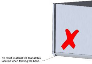
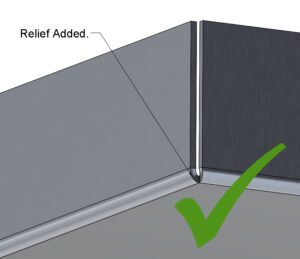
When producing a part with adjoining bends, special cuts must be made into the part to prevent material near the bend from tearing during the bending process. See below an example of an un-manufacturable bend with no relief and a part that has relief accounted for.
No Relief sheet metal part design
Relief added, sheet metal component design
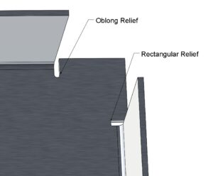
For bends where the flanges aren’t adjoining, there are a number of different relief types available for utilisation by designers, two of the most common types are shown below. Note that a good rule of thumb to follow for relief cut sizing is for the width to be at least the thickness of the material and for the length of the cut to exceed the radius of the bend.
Relief sheet metal part design
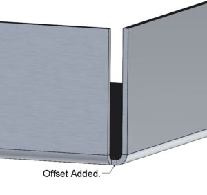
See below an example of a flange that has been offset to avoid the need for a relief cut.
Offset added sheet metal part design rules
It is important to consider whether the flange corners are to be closed or not, they may require a gap to allow for welding.
Weld gap sheet metal part design rules
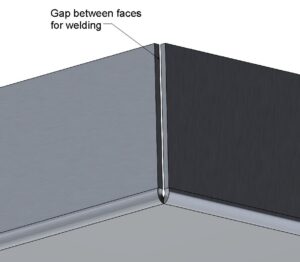
weld gap sheet metal part design rules
With the corners closed, there is still the option to weld the flanges together on the inside faces if required.
Sheet metal part design rules flange overlap
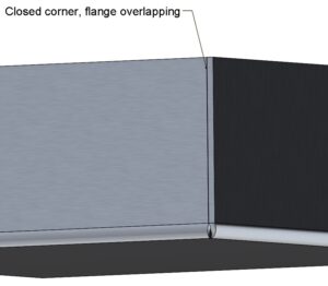
sheet metal part design rules flange overlap
5 Tips for bending sheet metal like a pro
Hole Features
Holes and slots which are dimensioned close to bends are susceptible to deforming following bending, see an example below of how a hole may appear the following bending if it is positioned too close.
sheet metal hole design rules
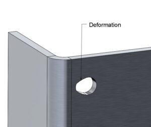
sheet metal hole design rules
To prevent this deformation, the minimum dimension for hole and slot edges from the bent edge should be applied as follows.
Sheet metal hole design rules
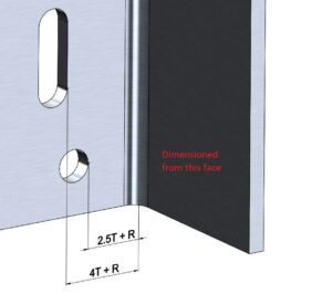
sheet metal hole design rules
Minimum hole edge from bend face = 2.5T + R
Minimum slot edge from bend face = 4T + R
Where T is the material thickness and R is the bend radius.
Ensure that holes and slots are positioned at least twice the material thickness from any material edge as shown below.
Sheet metal hole position design rules
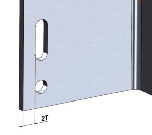
sheet metal hole position design rules
Roll bending vs. traditional bending process
Common mistakes to avoid in sheet metal fabrication
Edge Treatments
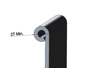
Some components benefit from having special features formed from the remaining edges, two of these main features are curls and hems.
Curls are circular rolls formed from the edge, these provide extra strength to the edge and also make it safer for handling by removing the sharp edge. The outer radius of a curl should be at least twice the material thickness, although this will vary depending on the manufacturer and their tooling for curling.
Curl edge treatment, sheet metal design rules
curl edge treatment, sheet metal design rules
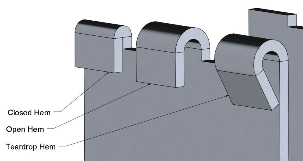
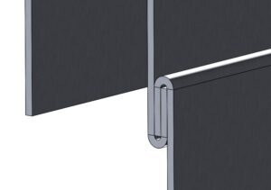
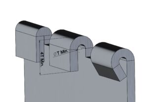
Hems are similar to curls but are formed into a U shape. They are useful for strengthening edges and can be used to connect parts together. There are three main types of hem, an open hem, a closed hem, and a teardrop hem.
Edge treatment, sheet metal design rules – hems

edge treatment, sheet metal design rules – hems
More press tonnage is required to create the closed hem. See an example below of how open hems can be used to connect two parts.
Hem assembly edge treatment, sheet metal design rules
hem assembly edge treatment, sheet metal design rules
Minimum dimensions for hems will vary between manufacturers, the following dimensions are for general guidance.
For open hems and teardrop hems, the minimum inside diameter should be at least the material thickness. For all hems, the return length should be at least 4 times the material’s thickness.
Edge treatment, sheet metal design rules
edge treatment, sheet metal design rules